

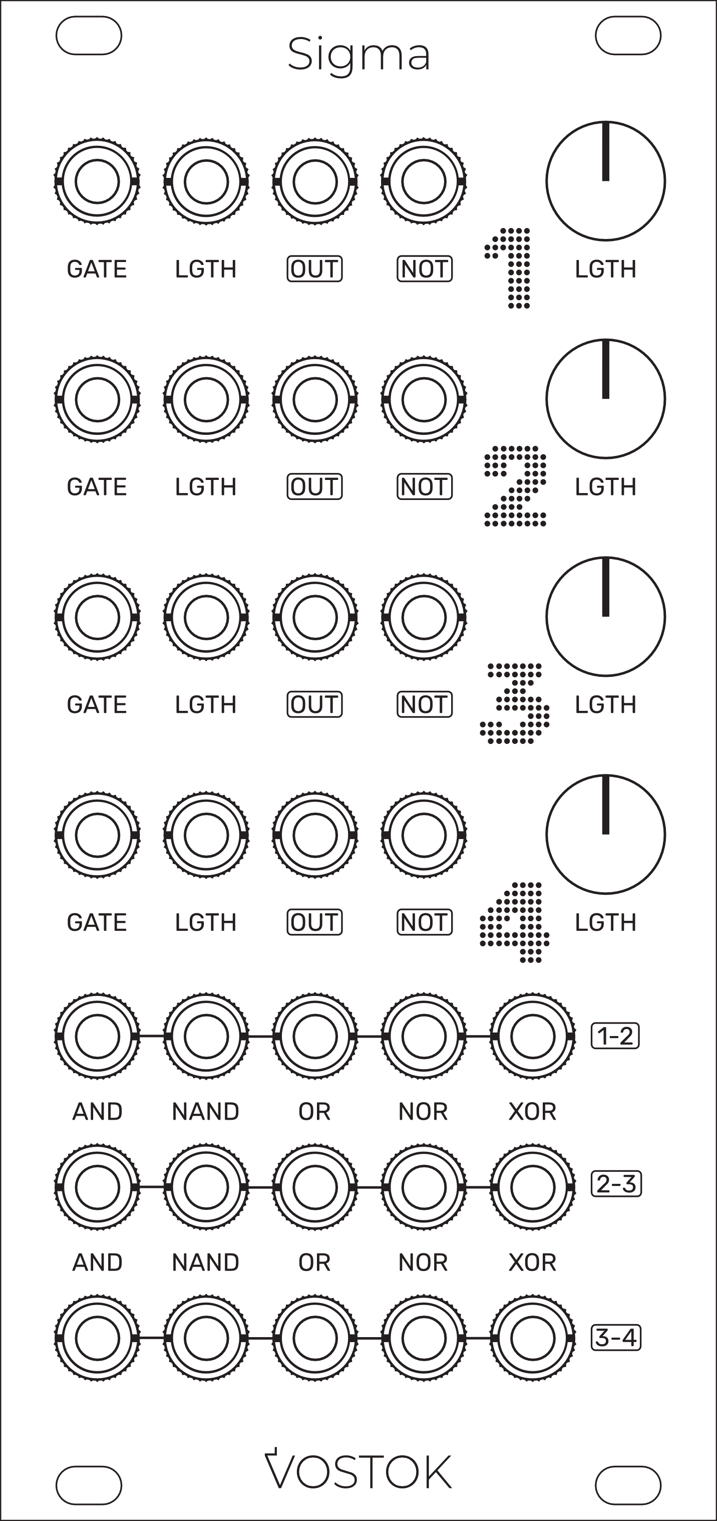
Sigma
Hybrid Rhythm Computer
User Manual
IMPORTANT SAFETY INSTRUCTIONS
Warning - When using electronic products, these basic precautions should always be followed:
Read all the instructions before using the product.
Do not use this product near water - for example, near a bathtub, washbowl, kitchen sink, in a wet basement, or near a swimming pool or the like.
This product, in combination with an amplifier and headphones or speakers, may be capable of producing sound levels that could cause permanent hearing loss. Do not operate for a long period of time at a high volume level or at a level that is uncomfortable.
The product should be located so that its location does not interfere with its proper ventilation.
The product should be located away from heat sources such as radiators, heat registers, or other products that produce heat. No naked flame sources (such as candles, lighters, etc.) should be placed near this product. Do not operate in direct sunlight.
The product should be connected to a power supply only of the type described in the operating instructions or as marked on the product.
Care should be taken so that objects do not fall and liquids are not spilled into the enclosure through openings.
LIMITED WARRANTY
Vostok Instruments warrants this product to be free of defects in material or construction for three years from the date of purchase (invoice required).
During that period, any malfunctioning unit will be repaired, serviced, and calibrated on a return-to-factory basis, with the customer paying the transit cost to Vostok Instruments.
Malfunctions resulting from wrong power supply voltages, backward or reverse power connections, abusive treatment, removing knobs, or any other obvious user-inflict faults are not covered by this warranty, and regular rates will apply.
Vostok Instruments implies and accepts no responsibility for harm to persons or apparatus caused through the operation of this product.
The device intended for repair or replacement under warranty should be shipped in the original packaging only. Vostok Instruments can not take any responsibility for damages caused during transport. So before sending us anything, contact us at vostokinstruments@gmail.com.
INSTALLATION
Sigma needs a power supply capable of providing 70mA on each of the +12V and -12V rails, and 12HP of free space in your case. We strongly recommend you to check the current consumption of your system on the ModularGrid website and your power supply capabilities before plugging in the module.
To install it, turn your case off and connect the supplied power cable to both the module and your Bus Board, minding the polarity so that the RED Stripe on the cable is oriented to the -12V line on both the module and the Bus Board. Please refer to your case manufacturers’ specifications for the location of the negative supply.
Always turn your case off before plugging and unplugging any Eurorack module.
INTRODUCTION
Sigma is a multi-channel gate processor with a strong focus on rhythm and time-event manipulation.
The module generates up to 23 simultaneous gate signals directly related to the four gate inputs, allowing you to fire an entire array of synced events in your patch by just moving pots and connecting cables.
The core of the module is composed of four identical CV-controlled gate-length processors that create exact copies of your gate signals with adjustable length.
The Logic section creates new events from each length-processed pair using analog Boolean circuits.
Pair Sigma with a trigger sequencer or clock generator, and a bunch of drum modules or voices to get a vast amount of new rhythmical patterns on the fly.
TECHNICAL SPECIFICATIONS
Size: 12HP
Current draw: +/-12V: 70mA, +5V: 0mA
Depth: 30mm (including power cable)
Input Impedance: 100kΩ
Output Impedance: 1kΩ
CV Inputs Range: 5Vp-p
Output Voltage: 5Vp-p
FIRMWARE DEVELOPMENT
Sigma is a hybrid module that counts with a digital gate-length processor core and an entirely analog logic section. The module would not exist without the marvelous work of our dear friend Eloi Flores from Winter Modular, who expertly coded the firmware for the length-processing functionality. Thank you, Eloi!
OVERVIEW
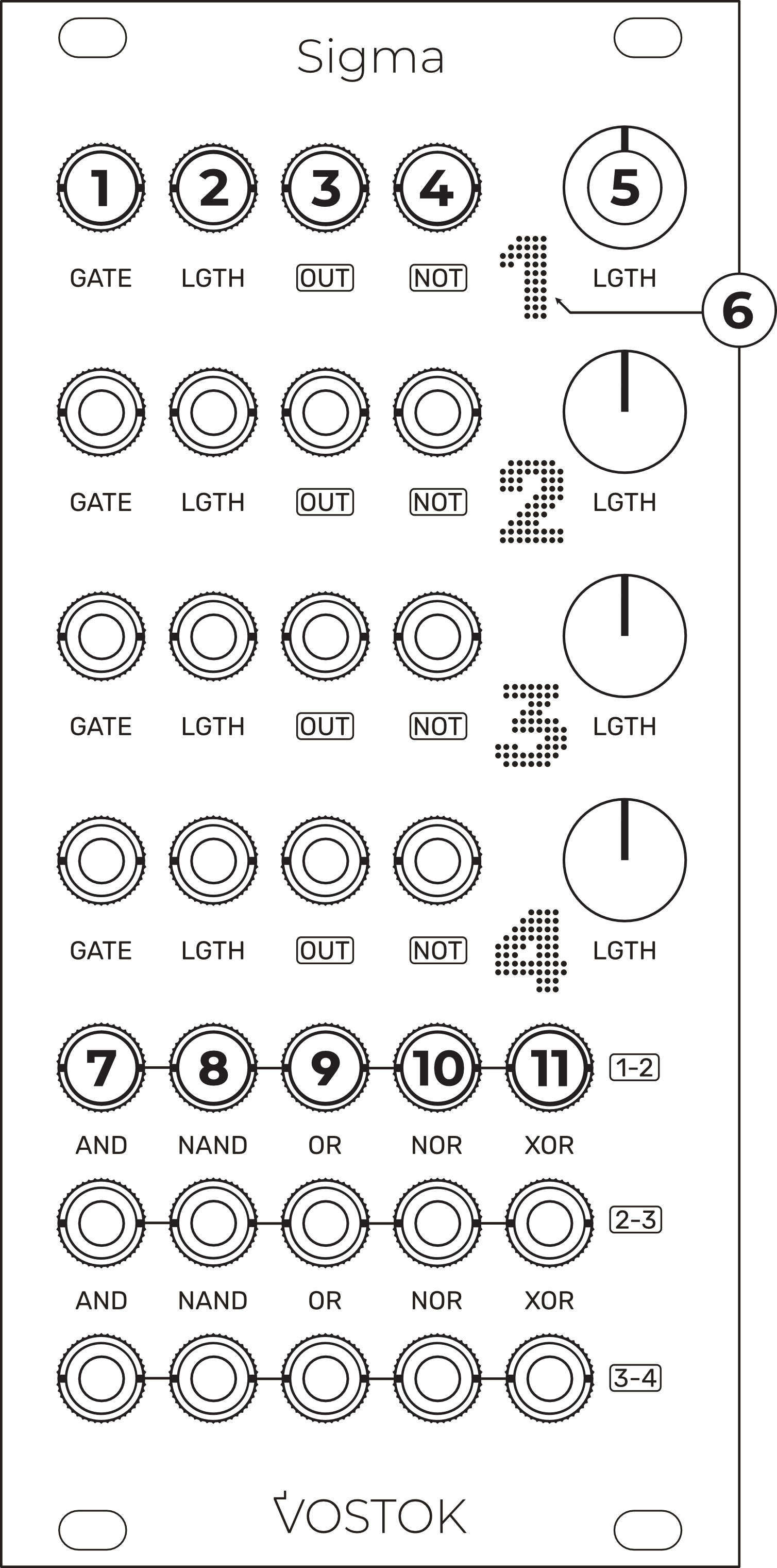
Gate Input.
LGTH CV Input: CV control over the gate length. Range: 5Vp-p.
Main Output: length processed gate signal output. Amplitude: 5Vp-p.
NOT Output: inverted version of the main output. Amplitude: 5Vp-p.
LGTH Pot: manual control for each channel gate length.
Output Signal LED indicator.
AND Output: output signal from the AND operation between the indicated pair of channels. Amplitude: 5Vp-p.
NAND Output: output signal from the NAND operation between the indicated pair of channels. Amplitude: 5Vp-p.
OR Output: output signal from the OR operation between the indicated pair of channels. Amplitude: 5Vp-p.
NOR Output: output signal from the NOR operation between the indicated pair of channels. Amplitude: 5Vp-p.
XOR Output: output signal from the XOR operation between the indicated pair of channels. Amplitude: 5Vp-p.
THE CONCEPTS BEHIND SIGMA
Sigma is our most special design to date. While it shares the multi-channel architecture and design layout of our other modules, its functionality relies on a combination of circuits that makes Sigma truly unique. To fully understand how it works, we should first look at the two main concepts the module is built on, so let’s get into it.
Gate Length
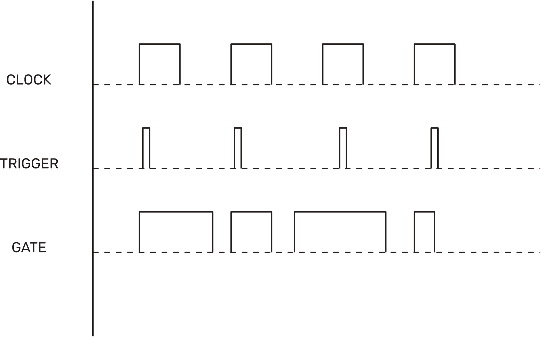
In our modular systems, we use different types of binary pulse signals, such as triggers, clocks, and gates. While they are very similar and we can swap their roles in the patch most of the time, each has a unique characteristic that justifies giving them their own name.
A clock signal, for example, is a steady stream of pulses that maintains equal, very accurate timing between them. Triggers, on the other hand, can be sent from many different sources. We use them to fire events, and their length is typically very narrow, as trigger inputs typically react only to the rising edge of the signals.
Gates are quite similar to triggers, but with one main difference: their length can vary. That means Gate signals can be held at their maximum value for a definite period, which opens the door to more use cases. The most common one is to work with sustained envelopes, allowing us to adjust how long a note is sustained by pressing a key on our keyboard.
In Sigma, we have four gate-processor channels designed to adjust the length of our incoming pulse signals accurately within a range of 1ms to infinity.
Boolean Logic
Logic circuits are an amazing way to create interesting patterns. While they can seem difficult to understand, logic circuits are quite simple and require very little effort to extract unique results that otherwise would be much harder to obtain.
Most logic circuits have two inputs and one output. The output gives us the result of a concrete operation between those two signals, creating a new one directly related to them. In a modular system, those two signals are usually rhythms. The operation we choose determines whether the output follows the moments when they coincide or when they differ.
In Sigma, we have five analog logic circuits: AND, NAND, OR, NOR, and XOR, for each available pair of channels plus a dedicated NOT output per channel. That alone gives us a total of 19 outputs; add them to each channel's main output, and we get 23 simultaneous gate outputs generated from only 4 inputs!
Length + Logic: Sigma’s Secret Sauce
Okay, so here is where things get interesting. The result we obtain from every logic circuit depends on the binary state of each source; that means whether the gate is high or low. If our length is fixed and equal on both channels, the result will always be the same as long as the input patterns don't change.
But what if we can change the length of the input patterns in real time? We would alter how long the gates stay high or low and their chance to coincide or differ; in other words, we would alter the result of the logic operation in real time, creating new patterns on the fly without changing the input.
To get a visual representation of that, let’s take the AND operation as an example. In an AND circuit, the output gate will only be high when both inputs coincide. If the lengths are equal, the result is always the same, but look what happens if we alter the length of just one of the sources.
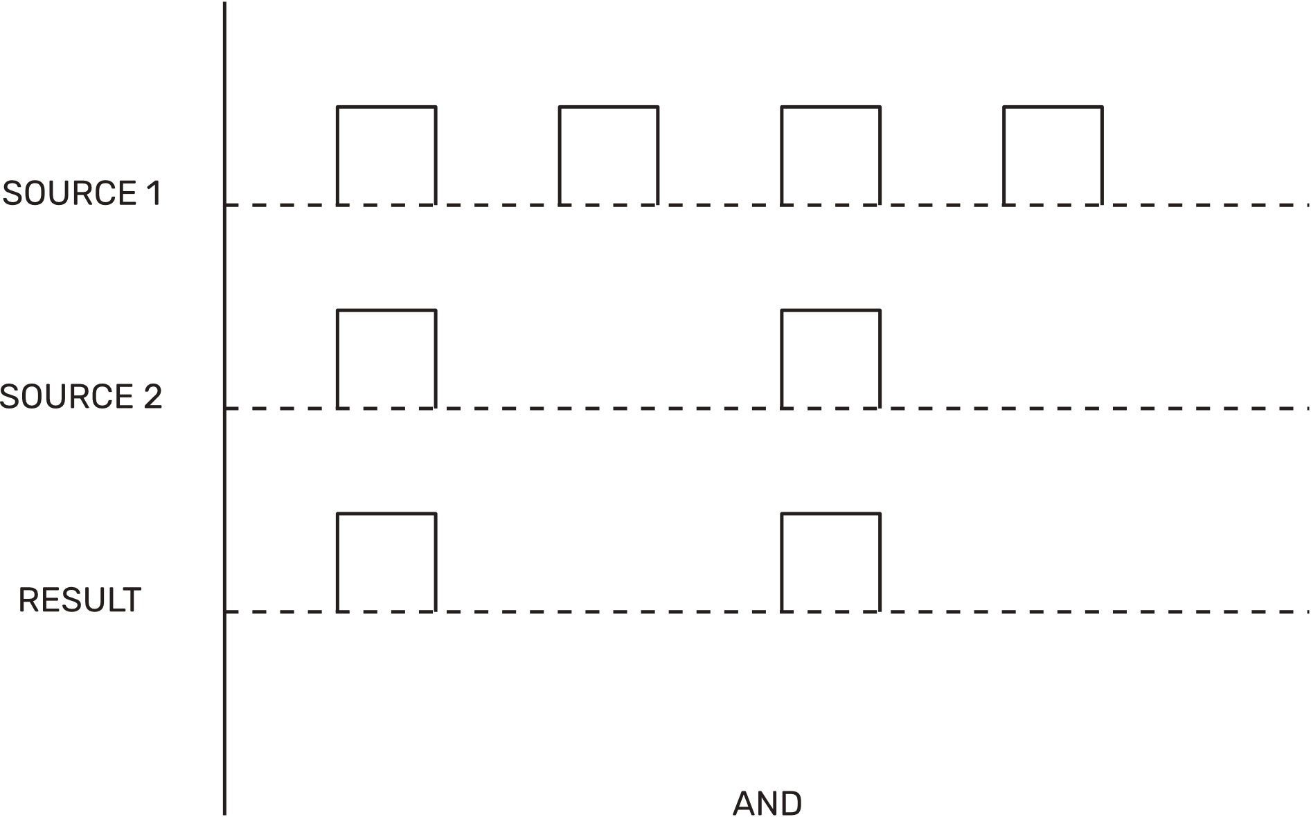
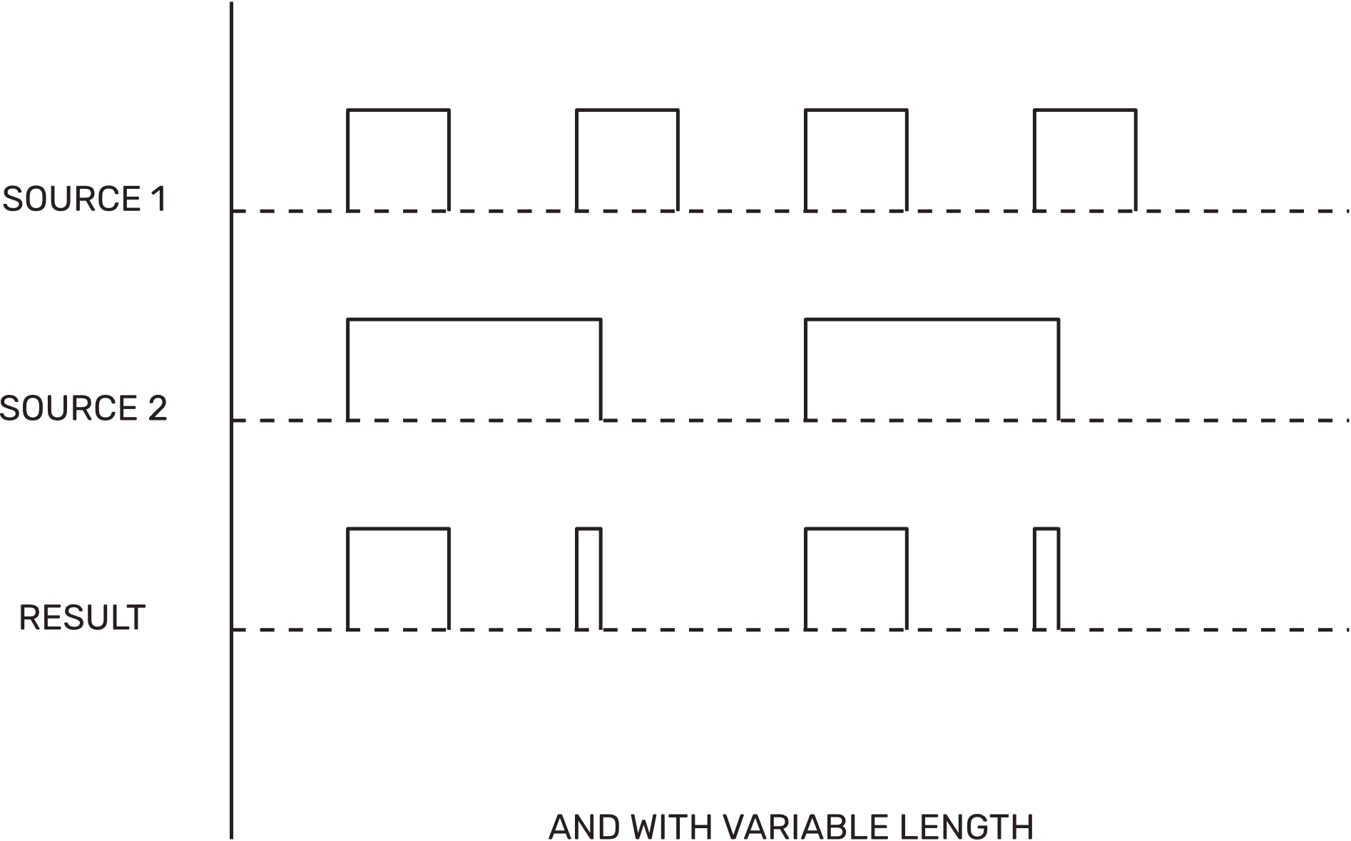
This is a playful, simple way to discover new patterns, with endless possibilities depending on which combination of logic outputs we use. Do we want to always stay on beat? Then the AND and OR outputs are our best friends. Maybe some off-beat hits? NAND and NOR will get us there. We don’t need to know the result; patch some cables, twist some knobs, and have fun!
Okay, we have the basics! Now let’s take a deeper look into the module’s functionality.
FUNCTIONAL MAP
Length Controls
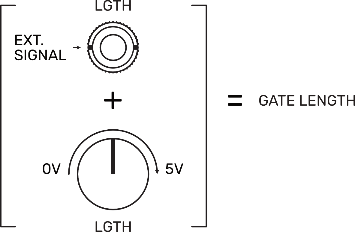
On Sigma channels, length is controlled by a positive voltage. The relationship between voltage and length is directly proportional, meaning that the higher the voltage, the greater the length. The Length controls of our channels (LGTH Pots) modulate the length by applying different values of positive voltage.
On the CV Inputs of our channels (LGTH Inputs), every voltage applied is summed to the voltage value set by the length controls. If we send a negative voltage to the input, it is subtracted from that voltage value, and the gate length is reduced. If the applied negative voltage is higher than the current value, the channel will remain at its minimum value until the voltage at its CV Input goes above zero and it starts working again.
Main Outputs
Sigma has 23 outputs. The outputs labeled as OUT are the main ones. These outputs provide an exact copy of the incoming pulse signal, with variable length controlled by the LGTH pot and its related CV input.
The length range of this output goes from a minimum of 1ms to 10s. The module is designed not to ignore any incoming pulse, so if the incoming pattern frequency is faster than the length value, the output will go low for 200us and immediately go high again. This behavior ensures the best results when using the logic outputs.
Be aware that at very high Length values, the Gate inputs of some modules can not react fast enough and will start losing hits. If that’s the case, just turn the Length pot down till your envelope reacts accordingly.
Infinite Mode
While we stated above that the maximum length is 10s, we implemented a way to sustain the gate indefinitely.
If we turn the LGTH pot fully clockwise and send a pulse signal to the input, the gate will stay high until it receives another pulse. Sending a new pulse will cause the output to react just as we explained in the previous section, making it go low for 200us and then come back high again.
LOGIC OUTPUTS
Sigma includes five different analog logic circuits for each channel pair, plus a dedicated NOT circuit per channel. Each output offers different behavior, with plenty of flexibility to try and combine. Let’s take a look at them.
NOT Output
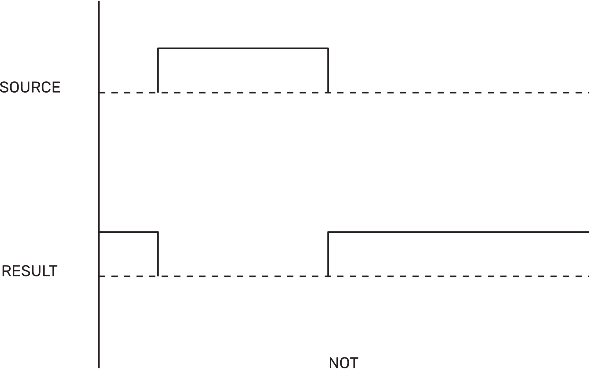
This output sends an inverted version of the main output, which means that when the main output is high, the NOT output is low, and vice versa.
Because the inversion happens after processing the length, the NOT signal can also serve as a delayed version of the main output, with the LGTH pot and its CV input acting as a Gate-Delay control.
AND Output
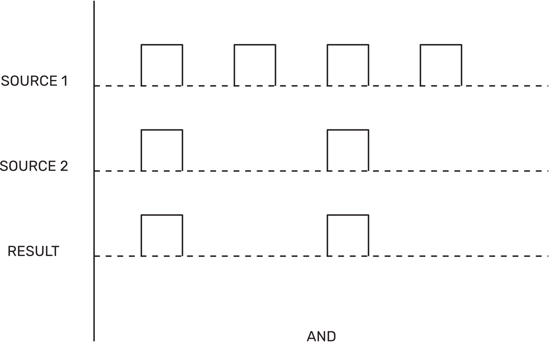
This output is high only when both inputs are high. This is the most selective operation, and it thins out both rhythms, keeping only the hits they share.
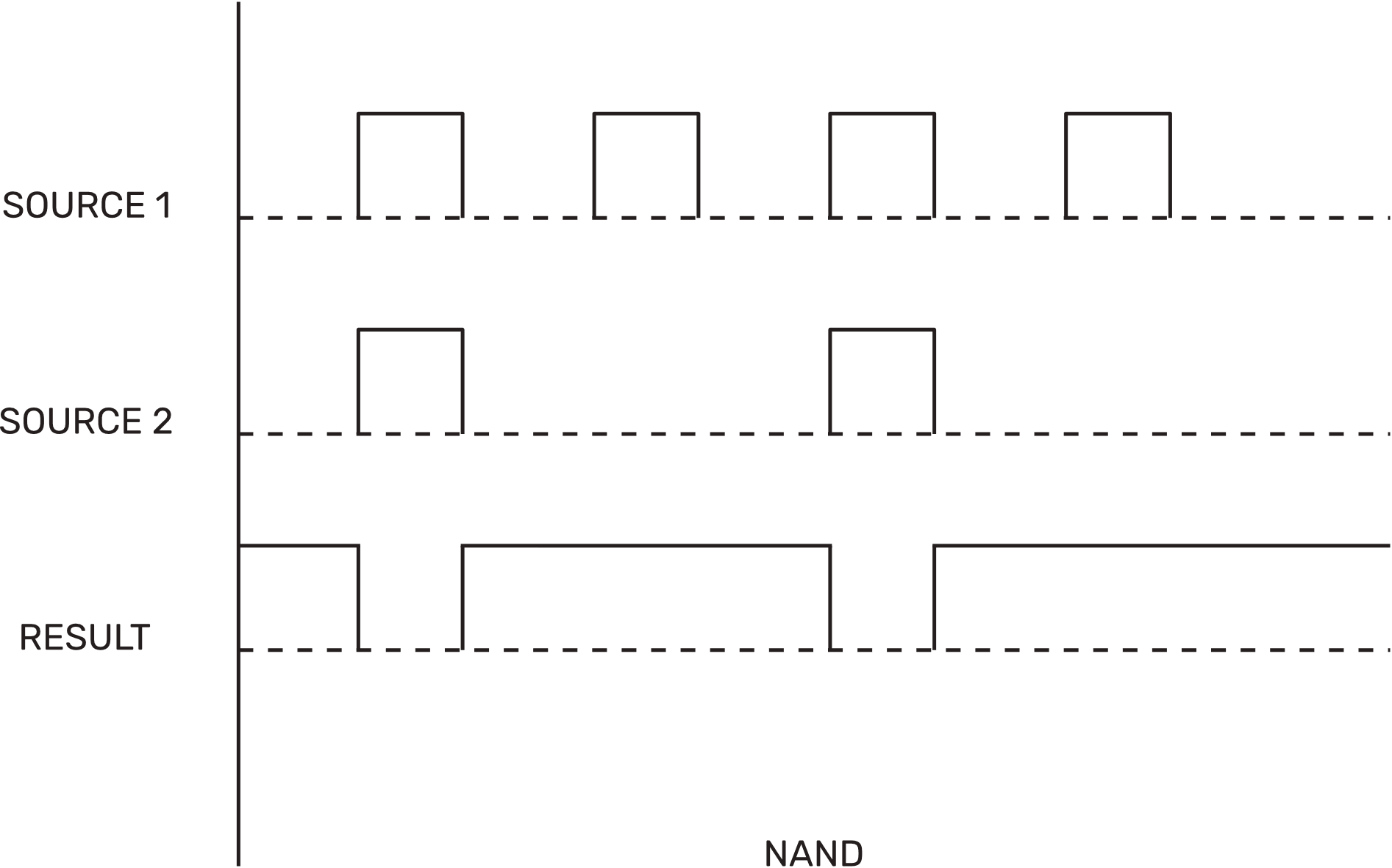
NAND Output
The opposite of AND. The output is high except when both inputs are high. It is dense, and it goes low at the exact moments AND goes high.
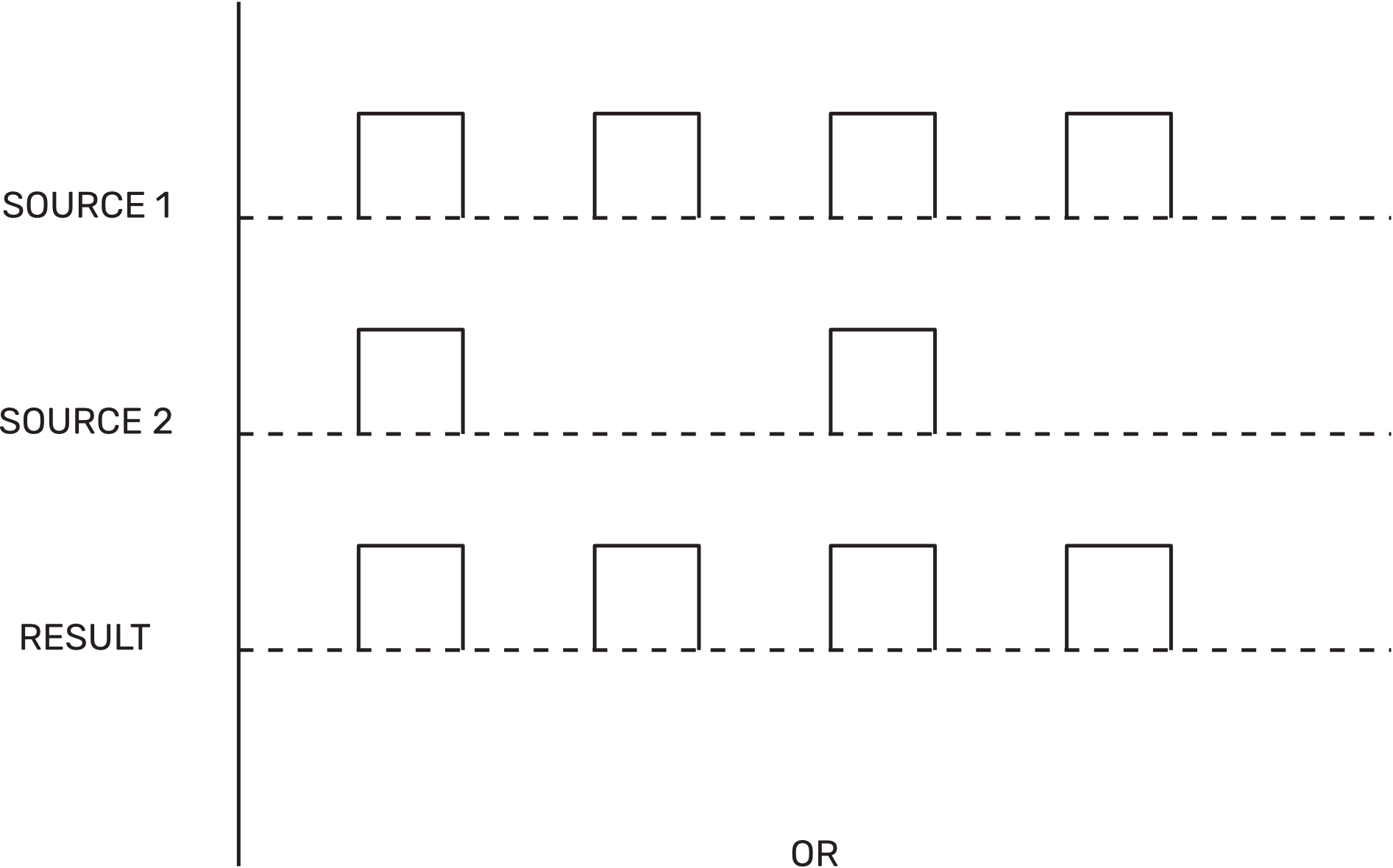
OR Output
The OR output is high when either input is high. It combines both rhythms into one, so nothing is lost and the result is busier than either source.
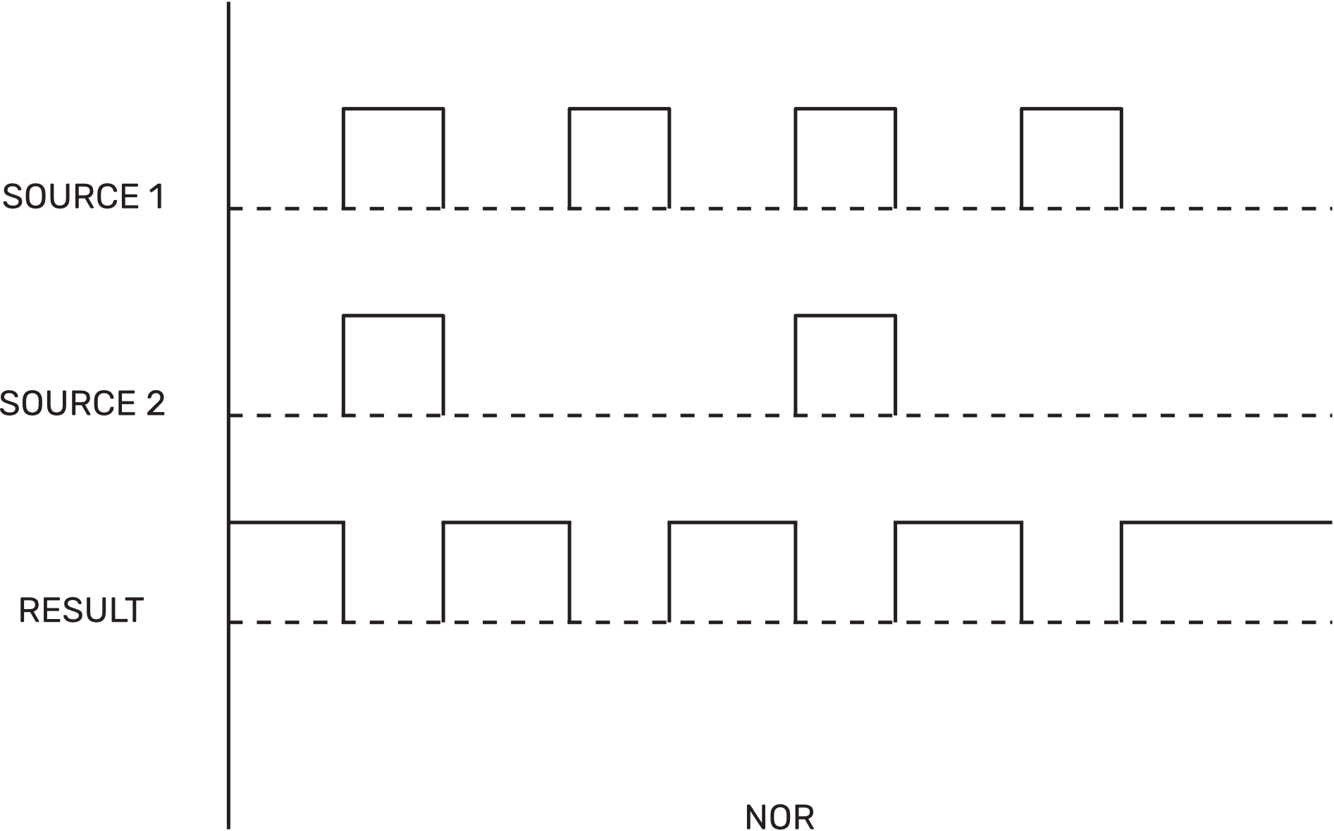
NOR Output
The opposite of OR. The output is high only when both inputs are low. It fills the silences, and it is often the sparsest of the operations.
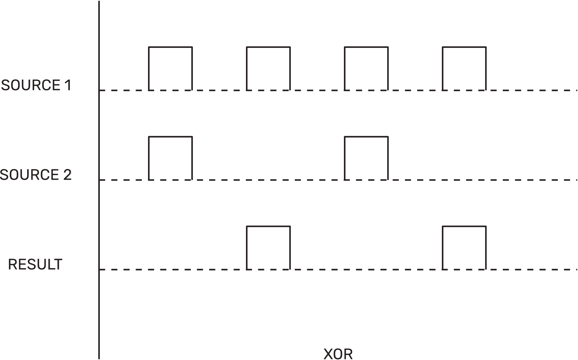
XOR Output
The output is high when the inputs differ. When both are high or both are low, it stays low. This makes it sensitive to the relationship between the two rhythms rather than to either one, and it tends to give the least predictable results.
As we discussed in previous sections, changing the length of each channel will alter the logic outputs and therefore create new patterns. While learning how each logic circuit works can be useful, we highly recommend playing with the module by just patching cables and turning knobs.
We designed Sigma to be a module about the joy of discovery, so we hope you enjoy using it as much as we did during its development!